
0-2000°C RESEARCH MATERIAL & HEATING TREATMENT'S LEADER
Ask for a free consultation Ask for technical support

Tel

WhatsApp/WeChat
Contact Us
All products are customizable, leave message immediately, we will reply as soon as possible.


Introduction:
1.The ultrasonic spray furnace system should be designed for versatility for the synthesis of nano core shell structures.
2.The system should consist of four main modules: aerosol generator, 3-zone heating furnace, electrostatic precipitation (precipitation) and four-channel mass flow controller.

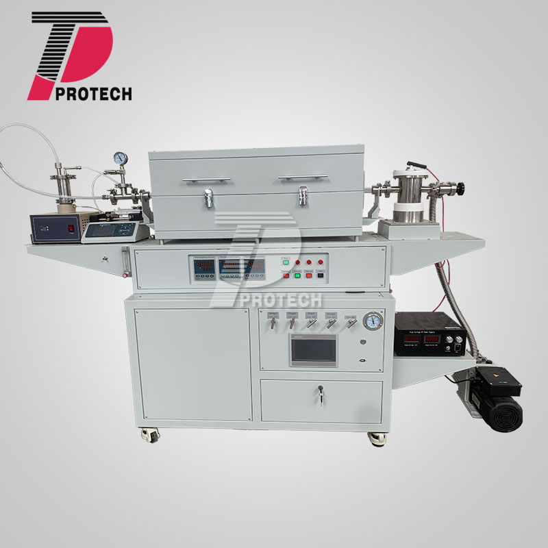
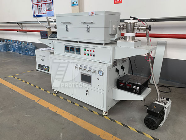
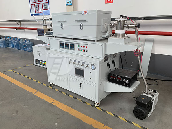
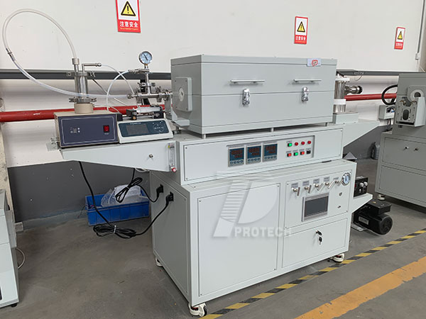
Real picture of 1.7 Mhz ultrasonic spray pyrolysis furnace
Technical Parameter:
|
Part I Aerosol generator |
|
|
Atomization device: |
Equipped with a 1.7MHz ultrasonic atomizer, the liquid can be atomized into liquid particles and introduced into a tube furnace. 20VAC, 1.7MHz ultrasonic atomizer • The liquid tank comes standard with 316 stainless steel,and sealed with a fluorine rubber seal; • Atomization amount can be set from 1 to 8, and the amount of atomization can be controlled by adjusting the size of the gear; • It can realize two functions of continuous operation atomization and regular operation atomization. The timing can be adjusted from 30 minutes to 180 minutes (adjust the gear every 30 minutes). |
|
Liquid injection system |
• A standard set of liquid injection pumps for automatic liquid feeding • The syringe pump is equipped with a plastic syringe with a maximum volume of 60ml for holding liquids; • Syringe pump speed adjustment range: 0.004ml / min—70ml / min |
|
Part II 3-Zone Heating Furnace |
|
|
Structure |
Heating section (tube furnace): The maximum temperature of the tube furnace can reach 1200 ° C. |
|
Working temperature |
Max. Temp. 1200C <= 1hr Contiously working temp. <= 1100C |
|
Recommended heating rate |
≤10℃/min, max. 20℃/min |
|
Heating Elements |
Fe-Cr-Al Alloy doped by Mo |
|
Hot Zone |
300+300+300mm If all three regions of the furnace are set to the same temperature, the constant temperature zone should be 600 mm with a temperature flexibility of ± 2 ° C. |
|
Temperature control system |
-Three digital temperature controller with 30 segments should be programmable for precise control of heating rate, cooling rate and dwell time. -The built-in overtemperature alarm and protection must allow operation at a temperature sensitivity of +/- 1 ºC. -It must have RS485 Communication Port.
|
|
Furnace Tube |
Using high-purity quartz tube Quartz tube size: Φ25 * 1400mm
|
|
Sealing Flange |
The left end is equipped with a KF series quick connection flange, which is connected to the atomization device, and a mechanical vacuum pressure gauge is connected through the tee. The right end is equipped with a KF series quick-connect flange, which is connected to the electrostatic collector
|
|
|
|
|
Tilt function |
The furnace must be tiltable to prevent fluid backflow. |
|
Part III Electrostatic precipitation (precipitation) |
|
|
High voltage power supply |
•Input: 208 ~ 240VAC single phase, maximum power 30W • Digital display voltage and current value, the maximum output voltage is 30KV, the maximum output current is 1 mA; • With arc protection circuit.
|
|
|
• The inlet of the collecting cylinder is a KF25 quick connector, and the air outlet is a quick connector with an outer diameter of Φ12.7mm; • A KF25 quick connector is reserved for the collection cylinder to evacuate the collection cylinder; • The positive pole and the negative pole are connected through a PTFE plate to achieve insulation; • The maximum volume of the collection cylinder is 700ml and the effective volume is 150ml.
|
|
Part IV 4 Channels MFC Controller (Optional) |
|
|
|
1. The equipment must have 4 channels and control the gases that will enter the furnace. 2. The equipment must have one LCD touch screen and must control 4 independent channels. 3. The equipment must be suitable for operation in the temperature range of 5-45 oC. 4. Equipment should be able to reach a maximum pressure of 3x10⁶ Pa. 5. The flow accuracy of the equipment should be ± 1.5% F.S for the full flow range. 6.The doubling accuracy of the equipment should be ± 0.2% F.S. 7. In the 4-channel system, three controllers should be able to control the gas flow at the limits of 0-200 sccm and one at 0-400 sscm. 8. One gas mixing tank should be placed under the system with liquid drain valve. 9. The system must include 4 stainless steel needle valves to control the flow of four different gases. 10. One of the four channels in the system is suitable for hydrogen, one for dry air, one for nitrogen and one for argon gases. |


